TransformerImpedance
# Impedance Voltage and Impedance Percentage
In order to properly analyze transformer performance, it is essential to have a solid understanding of transformer impedance. This is especially true with regard to voltage regulation and the transformer’s capacity to deal with fault conditions. An impedance in a transformer is a measure of the resistance to the flow of alternating current (AC) through its windings. When the transformer is in operation, it consists of both resistive (actual) and reactive (imaginary) components. In this section, we will delve into the concepts of impedance voltage and impedance percentage, both of which are essential characteristics for transformer design and application in electrical power systems.
# Impedance Voltage
The impedance voltage, also known as the short-circuit voltage, refers to the voltage required for the primary winding of a transformer to circulate the rated current through the secondary windings under short-circuit conditions. This parameter directly measures the transformer’s internal impedance, typically expressed in volts or as a percentage of the transformer’s rated primary voltage.
It is important to note that the impedance voltage is significant because it reflects the voltage drop that occurs within the transformer when it is subjected to load circumstances. Additionally, the transformer’s ability to restrict short-circuit currents is also significant. While a higher impedance voltage indicates a larger internal voltage drop and a stronger ability to reduce fault currents, it also has the potential to lead to voltage regulation characteristics that are less desirable under normal operating conditions.
# Impedance Percentage
By expressing the impedance voltage as a percentage of the transformer’s rated primary voltage, the impedance percentage is a dimensionless quantity that may be used to represent the impedance voltage. It provides a standardized measurement of the transformer’s impedance characteristics, regardless of size or rating, making it an essential parameter for transformer selection and system design.
The formula that can be used to determine the percentage of impedance is as follows:
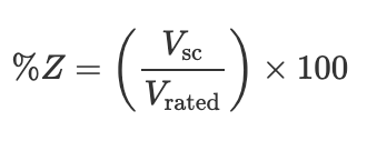
where Vsc denotes the impedance voltage (short-circuit voltage) and V_rated represents the rated primary voltage of the transformer.
# Method
# Two Winding Transformer
# Impedance Measurement
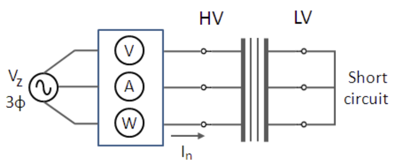 Positive sequence impedance test circuit for three-phase 2-winding transformer
The positive sequence impedance is measured from a standard short circuit test (see figure right). In this test, one set of windings is shorted (typically the LV windings) and a three-phase voltage source is applied to the other set of windings. The voltage is steadily increased until the rated phase current is measured.
The voltage at this point is called the impedance voltage. When the impedance voltage is expressed as a per-unit value (on the transformer rated line-to-line voltage), the impedance voltage is equivalent to the per-unit impedance, i.e.
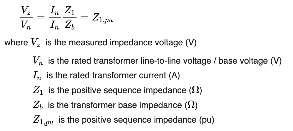
The impedance voltage is also often expressed as a percentage (Z%).